Technical information
FAQ / Definitions and explanations of our products and technology
Our products are almost all RoHS and REACH compliant. There are few exceptions, such as mercury relays or some special sensors.
The correct selection of the housing material is important for the durable of the product. The selected material have to permanently protect the components (reed switch) inside the sensor in order to ensure proper functioning.
Selection criteria:
- Minimum and maximum surrounding temperature
- Medium in which the sensor is used
- Maximum pressure in the medium
- Mechanical stress
Possible housing materials:
- Metal: stainless steel, brass
- Plastic: PA, PC, PP, POM, others on demand
We will be happy to advise you on the selection of your optimal housing material for your application.
The reed technology allows a non-contact switching of an electrical signal or voltage, with the help of a magnetic field. Here, a defined external magnetic field acts on a special ferromagnetic switching contact, also called reed switch or reed contact. This magnetic field is usually generated by a permanent magnet or a coil. Products based on this technique are also called Reed sensors.
Advantages of reed technology (reed sensors):
- Non-contact, low-wear switching process
- Long service life
- High switching frequency
- Cost-effective alternative to electronic switch
General technical data
Switching distance
The switching distance is the distance at which the reed switch is actuated by approaching the magnet. The length of the switching distance depends on the field strength of the magnet and the sensitivity of the reed contact.
Switching hysteresis
The switching hysteresis is the differential distance between the switching on and off points. It depends mainly on the type of reed contact.
Switching point accuracy
A very high repetition accuracy of the switching point is given for magnetic switches. It is in the range of approx. 0.02 mm at constant ambient conditions.
Response time (incl. bruise time)
Depending on the reed contact size, the response time is in the range of 0.6 and 3 ms.
Release time
Depending on the reed contact size, the relapse time is in the range between 0.05 and 2ms.
Switching speed
For magnetic switches with reed contacts up to 300 Hz, depending on the type and size of the reed contact. For switches with reverb element up to 100 kHz, depending on the version.
Vibration resistance
The mechanical vibration resistance is in the range from 10 to max. 30 G. With magnetic switches with built-in spring replacement contact, the vibration resistance is lower, magnetic sensors with reverberation elements are largely insensitive to mechanical vibrations.
Protection
IP 67, contact protection against dust ingress, water protection against immersion
IP 68, contact protection against dust ingress, water protection against immersion
Switching Capacity-Example
The max. switching power is the product of switching current and switching voltage. In the case of alternating current variables, the current and voltage must also be multiplied by the power factor cos φ. However, the individual limit values must not be exceeded. The working area of the reed switch is visible from the switching power hyperbole.
Max. Switching power of the reed switch = 30 VA.
At 24 V DC (DC) the following switching current must be adhered to:
IMAX = 30 VA: 24 v = 1.25 A.
Temperature range
-5 °c… + 60 °c (standard) extended temperature range on request-40 °c… + 150 °

Reed contacts can be used in almost all environmental conditions due to the materials used and the hermetically sealed design. Thus, the both switches in the contact area are coated with a very hard metal, mostly rhodium or ruthenium (with special switches also tungsten and iridium). This construction will achieve the long service life and reliable working method
The Reed contact is available in many different versions. The following parameters are different:
Switching capacity
This is in the range from 0.1 to 30 W. Even a short-term overload already leads to a failure. It should be noted that none of the specified values (voltage, current) will be exceeded for a short time either.
Switching current
This is the maximum allowed current when closing the reed contact. The higher the current, the greater the switching arc on closing and opening. If the current is too high, it can be used for bonding (welding) of the contacts, which means that the function is no longer available. The capacity of the connected circuit also negatively affects the service life of the reed contact. For relatively high switching signals, the current should be limited to the first 50 ns. From 50 V and 50 pF onwards, a lasting influence on the reed contact can already be created.
Transport flow
This specifies the maximum permissible current via the already closed contacts. This is higher than the Schaltsrom because the contacts are already closed.
Switching voltage
This is the maximum permissible voltage (DC or AC) that the contact is allowed to switch. Switching voltages above the arc limit.
Insulation resistance
The value measured above the open reed contact is typically in the range of 109 to 1014. This good isolation causes only the smallest leakage currents from Femto to Picoampere. Test equipment in which high impedance must be switched between several inputs is therefore feasible.
Contact capacity
This is the capacity between the contacts when the switch is open. The values are approx. in the range of 0.1… 0.3 pF. The low contact capacity is a special feature of Reedkontakten. This allows impedance to transmit alternating voltage signals at low overtalk.
Tightening sensitivity
This value specifies the closing point of the switch. It is usually indicated in ampere coils (AWan). A defined measuring coil is used to determine this value. For this purpose, the current of the measuring coil, in which the reed contact to be used is located, is increased to the switch-on point. The calculated value of the sink is then multiplied by the number of coils = tightening sensitivity. The specification is generally valid for 20 °c.
Switching hysteresis
Is the ratio in % between the on and off point
Closing time (incl. bounce)
This is the time required to close the contact (until the end of the bouncing). Most reed contacts have a closing time of 100 – 500 s.
Release time
This is due to the reed contact in the range between 0.05 and 2 ms.
Switching speed
Up to 300 Hz
Vibration resistance
The mechanical vibration resistance is in the range from 10 to max. 30 G.
Temperature range
Approx.-20 °c… + 150 °c, types also with extended temperature range
normally open (Form A)
In retirement, the Reed contact is open. When a magnet is placed near the switch, the paddles move towards each other – the switch closes. If the magnet is removed, the reed contact reopens.
normally closed (Form B)
A closed reed contact opens when a magnet is brought near and closes when the magnet is removed.
change over (Form C)
A so-called SPDT (single pole double throw) is a switching contact, which changes from the rest to the working contact when a magnetic field is created.
The reed switches (so also all products that contain them, such as reed sensors) may only be operatedwithin the electrical limits specified in the data sheet (switching current, switching voltage, switching power). A short-term exceedance of one of these limits can lead to a reduced service life or even to a failure .
the values specified in the data sheets apply to pure ohmic loads ! In most cases, however, the loads are fraught with inductive or capacitive components or lamp loads are switched. In all these cases, the reed contacts must be protectedagainst the occurrence of voltageand current peaks in order to avoid rapid wear or premature failure. See the point protection circuit.
Inductive loads (e.g. motors)
When switching alternating current, an RC link must be connected parallel to the reed switch and thus in series with the load.
When switching direct current, a freewheel diode must be connected parallel to the load. The polarity must be carried out in such a way that the diode locks at the normally adjacent operating voltage and short-circuits the voltage peak, which always occurs in the opposite direction when the reed switch is opened.
Capacitive loads
In the case of capacitive loads and lamp loads, increased inrush currents occur which can lead to disturbances up to the welding of the contacts. When switching charged capacitors (e.g. also cable capacities), a sudden discharge occurs, the intensity of which depends on the capacity and the length of the supply line to be considered as series resistor to the switch. The discharge current tip is largely reduced by a series resistance to the capacitor. It should be as large as possible to limit the discharge current to a permissible value.
Incandescent filaments have a resistance in the cold, i.e. in the non-switched state, which is about ten times smaller than in a glowing state. This means that when the power is switched on, if only for a short time a ten times higher current flows than in the glowing, static state of the lamp. This 10-times inrush current surge can be reduced to an acceptable level by means of a series-switched power limiting resistor. One possibility is the parali switching of a resistor to the reed switch, which constantly preheats the lamp thread in the switched off state so far that it just does not glow.
external magnetic fields can lead to malfunction or permanent changes. A magnetic shielding in reed relays can shield the reed switch from these fields.
The reed technology is based on a reed switch, which switches by magnetic influence. Our products are precisely matched to each other for this interaction. An additional external magnetic field can influence this and lead to malfunctions. Therefore they keep enough distance from magnetic fields, E. G. transformers, Motors,…
By falling or similar shock effects, the function of the sensors and relays can be severely affected, or lead to a failure.
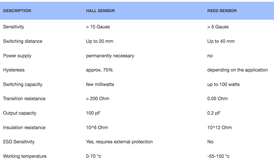
| Description | Hall sensor | Reed sensor |
|---|---|---|
| Sensitivity | > 10 Gauss | > 5 Gauss |
| Switching distance | Up to 20 mm | Up to 40 mm |
| Power supply | permanently necessary | no |
| Hysteresis | approx. 75% | depending on the application |
| Switching capacity | few milliwatts | up to 100 watts |
| Transition resistance | > 200 Ohm | 0.05 Ohm |
| Output capacity | 100 pF | 0.2 pF |
| Insulation resistance | 10^6 Ohm | 10^12 Ohm |
| ESD Sensitivity | Yes, requires external protection | No |
| Working temperature | 0-70 °c | -55-150 °c |

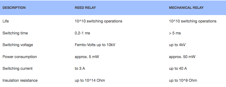
| Description | Reed relay | Mechanical Relay |
|---|---|---|
| Life | 10^10 switching operations | 10^10 switching operations |
| Switching time | 0.2-1 ms | > 5 ms |
| Switching voltage | Femto-Volts up to 10kV | up to 4kV |
| Power consumption | approx. 5 mW | approx. 50 mW |
| Switching current | to 3 A | up to 40 A |
| Insulation resistance | up to 10^14 Ohm | up to 10^9 Ohm |

In many of our products permanent magnets are installed. The magnetic material used should be adapted to the respective application. Each material has different strengths of magnetic genes.
| Material | Flux density | Specifics |
|---|---|---|
| Ferrite | Low | Inexpensive |
| AlNiCo (aluminium-nickel-cobalt) | Means | High temperature up to 500 °c |
| SmCo (Samarium-cobalt) | High | High temperature stability |
| NdFeB (Neodymium-iron-boron) | Very high | corossion prone |

